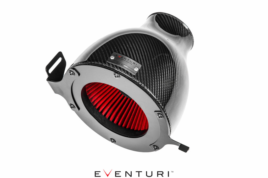
The Eventuri 8V RS3 intake system consists of a number of components engineered to perform a specific purpose and fabricated to the highest of standards. Here are the details for each component and the design ethos behind them:
Each intake system consists of:
- Carbon Fibre Venturi Filter Housing
- High Flow Urethane Cone Filters
- Carbon Fibre inlet Duct
- Carbon Fibre or Metal Turbo Tube
- Carbon Fibre Connecting Tube
- Laser Cut Stainless Steel Brackets
- Silicon Couplers and Reducer
Carbon Intake Housing Assembly

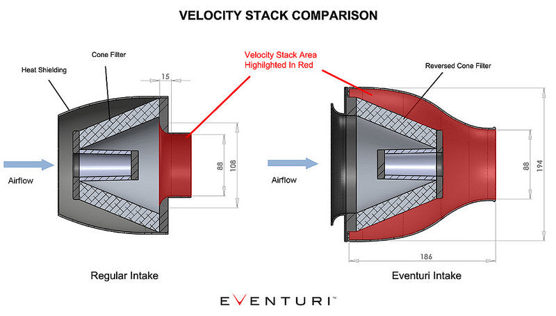
The filter housing comprises of a high flow filter, aluminium cowl, laser cut brackets and the carbon pod itself. The carbon pods shroud the reverse mounted filter and smoothly shape the airflow down to the intake tubes. This smooth reduction in cross sectional area invokes the Venturi effect where the airflow accelerates whilst maintaining laminar conditions. It can be thought of as a large velocity stack - below is a diagram to show the comparison between Eventuri patent pending design and a regular intake system. Further details can be read in the Technology page.

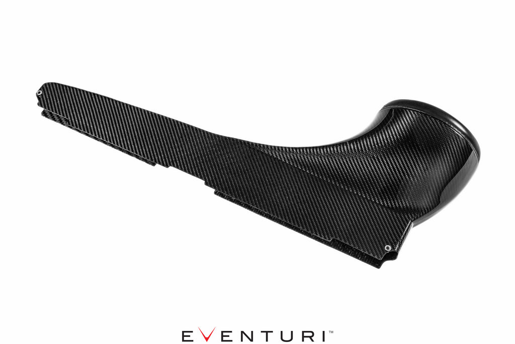
Carbon Fibre Intake Duct

The duct channels ambient air from the slam panel area to the filter housing. It fits inside the OEM ducting system and smoothly transitions to the circular filter housing shape. In order to ensure a good seal against engine bay heat - it also has a flexible rubber edging around the opening which presses against the filter housings creating the desired seal yet allowing the housing to move with the engine. The duct was designed to have the maximum internal volume possible within the given geometry of the engine bay. This ensures that the filter housing is able to draw with minimum restriction.
Carbon Fibre Intake Tubes


Eventuri intake tubes are again crafted from 100% prepreg carbon fibre. Each tube has an internal diameter of 88mm - the stock tubing is just 77mm in diameter. This enlarged diameter allows the turbo to operate with less restriction and also allows larger/hybrid turbos to run even better. The tubes smoothly carry the airflow to the turbo by ensuring there are no sharp or sudden bends. The smooth bend geometry ensures laminar flow is maintained from the filters to the exits.
The combined system ensures that airflow remains full and consistent to the turbo - minimising the occurrence of turbulence. The following flow simulation shows how smooth and full the flow is within the inlet tubes before the turbo. There is some circulation in the duct as is expected but once the flow enters the tubing, this is smoothed out and allows the turbo to operate more efficiently.


